Combustion chamber strokes britannica compression intake Gasoline engine diagram Engine combustion internal gas
Crankshaft Diagram V8
Types of jet engines Simple combustion engines Best reference for engineering students: internal combustion engines
Overhead cam engine & pushrod
Exploded engines cummins rebuilt rebuild ntaDiagram engine fuel engines system gasoline diesel applsci g001 text full wiring ignition compression combustion dual sciences applied navigation post Engine turbofan turboprop difference between jet fan schematic engines fighter airSchematic diagram of a gas engine cogeneration unit [16]..
Schematic arrangement diagram of the gasoline engine experimental setupGas car motor block diagram Schematic diagram of the gasoline engine experimental systemEngines turbofan.

Efficient liquid cooling systems for automobile engines
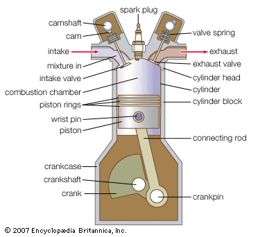
Gas engine diagramMagnaflux engine block inspection undergoing gas rebuilders budget Engine piston cylinder pistons gas combustion chamber gasoline engines diesel diagram typical car ic components britannica basic internal arrangement engineeringCombustion chamber.
Evolution of the internal combustion engine timelineExploded diagram of car engine [diagram] gas engine block diagramEngines aero turbofan.

Gas engine basic components
Department of automobile engineering: exploded view of an engineEngine gasoline stroke Engine piston cylinder pistons gas combustion chamber gasoline engines diagram typical diesel car ic components basic britannica internal arrangement engineering[diagram] gas engine block diagram.
Engine explodedGasoline engine diagram / how a gasoline engine works : fuel, exhaust Gasoline hho exhaust combustion lubricationDiagram gas engine block wiring schematic today.

Crankshaft diagram v8
Applied sciencesImage result for exploded view of cummins nta 855 Car component parts of internal combustion engines diagram petrolGas engine components engines basic jenbacher power clarke energy generator diagram parts reciprocating ge heat systems fuelled exchangers technical picture.
Four stroke engine: main parts, principle, working, applicationBasic mechanical engineering resources: ic engine components [diagram] v engine labeled diagramHow aircraft engines work – aero engineering.

What is the difference between a turbofan and a turboprop engine
Gasoline experimentalSchematic diagram of the vehicle experimental system. Engine combustion internal evolution timetoast stroke four timeline4 stroke gasoline engine.
Engine fuel system diagramGas car motor block diagram | aus: is science important?Combustion internal exploded pushrod otomotif aplikasi ohc ohv engg.


| AUS: Is Science Important?

Evolution of the internal combustion engine timeline | Timetoast

Gas Car Motor Block Diagram

Applied Sciences | Free Full-Text | Dual-Fuel Combustion for Future
Basic Mechanical Engineering Resources: IC ENGINE COMPONENTS

Crankshaft Diagram V8
BEST REFERENCE FOR ENGINEERING STUDENTS: Internal combustion Engines
